Designer must see! Some design problems and solutions for UVC LEDs
Date:2018-07-26
With the increased performance of UVC LEDs, this relatively new technology is rapidly evolving in life sciences and environmental monitoring instruments. As with all emerging technologies, designers must be aware of some fundamental differences from existing solutions rather than simply replacing them.
As the performance of UVC LEDs (deep ultraviolet LEDs) increases, the use of this relatively new technology in life sciences and environmental monitoring instruments is rapidly evolving. As with all emerging technologies, designers must be aware of some fundamental differences from existing solutions rather than simply replacing them. This allows designers to take full advantage of the full benefits of UVC LEDs. After careful consideration, UVC LEDs can reduce the footprint and power consumption, thereby increasing the cost of ownership for the end user.
Application of deep ultraviolet LED in instruments
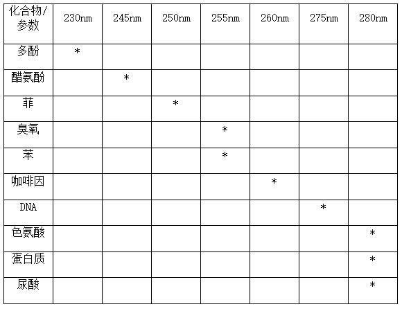
The interest in UVC LEDs in spectroscopy applications is increasing as they address market trends in miniaturization, cost reduction and real-time measurement. Unlike xenon or xenon flash lamps, LEDs emit a narrow spectrum in which all light output from the device is available for measurement. Users can select specific peak wavelengths of interest based on application requirements. In specific applications, standard measurement methods for 254 nm mercury lamp emission lines have been developed. For example, water and air quality measured according to EPA standards requires LEDs to approach the 254 nm peak wavelength. Table 1 lists some of the important organic compounds in life science research, drug production, and environmental monitoring that can be identified by spectroscopy.
Table 1. Peak absorption wavelength of common organic compounds
Another major criterion for instrument source selection is the peak wavelength light output. Because LEDs have only a single peak, unlike other UV lamps, the light output is concentrated at a specific wavelength. Absorption spectroscopy applications typically require low levels of light output - 1 mW or less. However, in the case where the flow cell is isolated from the light source, a higher output is required due to significant light attenuation before the signal reaches the flow cell. This can increase the light output required by the LED to more than 1mW. In the fluorescence spectrum, the signal intensity is proportional to the light intensity. The excitation power depends on the concentration level of the tracer that needs to be detected, so in these applications, the light output required for a single LED can be greater than 2 mW. Figure 1 compares the irradiance between the UV sources commonly found in instruments. Although the input power of the LED is much less, the required UVC wavelength is more irradiant than other sources, making it a more efficient source for specific measurements.

figure 1. This figure compares the irradiance of UVC LEDs, Xenon flash lamps, and xenon lamps.
After selecting the wavelength and light output, another important parameter is the viewing angle as it affects the instrument's optical system. Broadly speaking, there are two options - narrow or wide angle. The former is achieved with a ball lens and the latter with a flat window. The narrow angle allows high intensity light to be obtained in a small area. This type of package is typically used when focusing light directly into the instrument.
The flat window package has a wider range of radiation, allowing for greater tolerance when aligned with the fiber for remote coupling. It is especially useful in applications where the flow cell must be isolated from light sources and electronics, such as monitoring high temperature chemical processes or chromatographic separations using highly volatile solvents. In fact, narrow-angle ball lenses keep components in the instrument to a minimum, while flat windows increase design flexibility.
Optimizing the drive current requires the designer to balance the light output with the life of the application. Driving the LED at a current lower than the manufacturer's rating reduces the light output, but it also increases the life of the light source. In applications that require high LED output power, some end users choose to operate the LEDs with currents above the data sheet specifications. Increasing the drive current in this way can increase the light output, but it can also cause some performance risks.
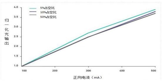
Overheating is a common problem that can have a negative impact on the light output and lifetime of an LED. Thanks to the instant switching function of the LEDs, the LEDs can be quickly turned on and off in a periodic manner. Fluorescent applications typically require higher light output, and pulse mode (duty cycle) is often used to increase LED current more safely. The duty cycle is the ratio of the energization time to the total time in one pulse cycle. For example, an LED that operates at a 50% duty cycle has exactly half the time to turn it off and on. Figure 2 shows the normalized light output for various drive currents and duty cycles.
figure 2. Here we see the effect of different duty cycles on the normalized light output, while the turn-on time is constant at 500μs. The normalized power is the relative optical output power of the light output relative to the maximum rated operating current of 100 mA (plus a suitable heat sink).
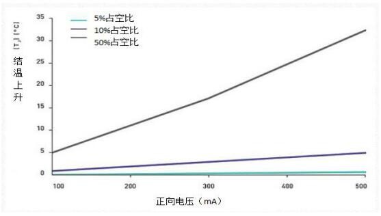
Operating the LED at high currents affects the LED junction temperature, which affects lifetime and light output. Optimizing the duty cycle minimizes the effect of the drive current on the junction temperature, thereby maintaining the performance of the LED. Figure 3 illustrates the effect of duty cycle on maintaining LED junction temperature. By operating at 5% duty cycle, more than three times the light output (as shown in Figure 2) can be achieved with minimal effect on junction temperature.
image 3. The graph shows the effect of different duty cycles on junction temperature, with the turn-on time kept constant at 500 μs.
Overheating can have a negative impact on the light output and lifetime of the LED. In the long run, this heat will reduce the life of the LED. Thermal management is very important when designing UVC LEDs because of the greater proportion of energy converted to heat compared to longer wavelength LEDs. Proper thermal management keeps the junction temperature at the low temperatures required for a given application and maintains the performance of the LED. In addition to passive and active cooling, the selected PCB can achieve better heat dissipation.
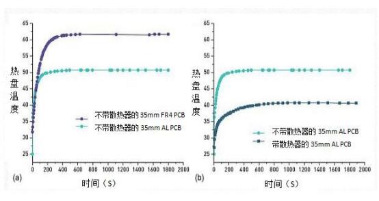
Figure 4. Compare the hot plate temperature of FR4 and aluminum core PCB without heat sink (a); the hot plate temperature of contrast ribbon and aluminum core PCB without heat sink (b).
FR4 is one of the most commonly used PCB materials because of its relatively low cost, but its low thermal conductivity. In systems with high thermal loads, metal core PCBs have better thermal conductivity and are a better choice. As the need for heat dissipation increases, designers tend to increase PCB area and add heat sinks for good thermal management. If further heat dissipation is required, designers can use more active cooling technology.
As the performance of UVC LEDs increases, designers are taking advantage of design flexibility for spectroscopic instruments and disinfection reactors. The advantages of LEDs in these applications enable a more compact, efficient, and cost-effective design. As this technology continues to evolve, smart designers will find more ways to use the
【Close】


 +86-760-22115926 Anna Zhang
 gaea668@263.net

 Chinese
 English
 TEL:
TEL:  Email: